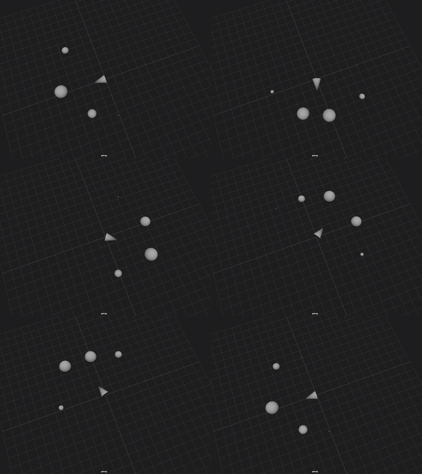
We’re going to make a cone and some spheres. As the cone’s Y-axis points toward each sphere, the sphere will scale.

Make a poly cone (driver). Rotate it 90 in X so it’s “pointing” along the xz (“ground”) plane.
drvr = cmds.polyCone(radius=0.5, height=1.0, name='driver')[0]
cmds.xform(drvr, ro=[90,0,0])
Create a vectorProduct node with the “Vector Matrix Product” operation, to isolate the driver node’s matrix . We can set the input1 vector to [1,0,0] to return the first row (x axis) of the matrix in the output attribute, [0,1,0] to return the second row (y axis), and [0,0,1] to return the third row (z axis).
driver_axis = 1 # y axis
vp_drv = cmds.createNode('vectorProduct', name='vpn_driver')
cmds.setAttr(vp_drv+'.operation', 3) #vector Matrix Product
cmds.setAttr(vp_drv + '.normalizeOutput', 1)
#isolate driver axis as output vector
cmds.setAttr(vp_drv+'.input1'+['X','Y','Z'][driver_axis], 1.0)
cmds.connectAttr(drvr + '.worldMatrix', vp_drv + '.matrix')
To get the fourth row of the driver’s worldMatrix, I recently found out that one can use a VectorProduct node with input1 set to [0,0,0] to isolate the translation row. (thanks @yantor)
vp_drv_pos = cmds.createNode('vectorProduct', name='vpn_driver')
cmds.setAttr(vp_drv_pos+'.operation', 3) #vector Matrix Product
cmds.connectAttr(drvr+'.worldMatrix', vp_drv_pos+'.matrix')
Make some targets: poly spheres in a circle around the origin on the XZ plane, between 0 and 10 units away from the origin.
for i in range(count):
    target = cmds.polySphere(radius=0.25)[0]

    # just on xz plane to test
    cmds.xform(target, ws=1, t=[
        ((0.5 - random.random()) * 10),
        0,
        ((0.5 - random.random()) * 10)
    ])
We don’t need the target nodes’ matrix axes, but we do need their world translation, so we get that with a decomposeMatrix.
dm_target = cmds.createNode('decomposeMatrix', name='dmn_'+target)
cmds.connectAttr(target+'.worldMatrix', dm_target+'.inputMatrix')
Then subtract target position minus driver position to get the vector between the driver and the target.
pma_target = cmds.createNode('plusMinusAverage', name='pma_'+target)
cmds.setAttr(pma_target+'.operation', 2) #subtract
cmds.connectAttr(dm_target+'.outputTranslate', pma_target+'.input3D[0]')
cmds.connectAttr(vp_drv_pos+'.output', pma_target+'.input3D[1]')
A “no operation” vectorProduct node with the normalizeOutput attribute set to normalize the vector between driver and target.
vp_norm = cmds.createNode('vectorProduct', name='vp_norm_'+target)
cmds.setAttr(vp_norm+'.operation', 0) #No Operation
cmds.setAttr(vp_norm+'.normalizeOutput', 1)
cmds.connectAttr(pma_target+'.output3D', vp_norm+'.input1')
A vectorProduct node with the “dot product” operation. This is the core of this whole setup.Two vectors pointing in the same direction have a dot product of 1.0, perpendicular vectors have a dot product of 0.0, and vectors pointing in the opposite direction have a dot product of -1.0.
vp_dot = cmds.createNode('vectorProduct', name='vp_dot_'+target)
cmds.setAttr(vp_dot+'.operation', 1)
cmds.setAttr(vp_dot+'.normalizeOutput', 1)
cmds.connectAttr(vp_drv+'.output', vp_dot+'.input1')
cmds.connectAttr(vp_norm+'.output', vp_dot+'.input2')
We’ll clamp out the negative values so we’re just using the values from 0 to 1 with a setRange node, and the output in this example will be remapped from 0.1 to 3.0.
sr_target = cmds.createNode('setRange', name='srn_'+target)
cmds.setAttr(sr_target+'.minX', min_size)
cmds.setAttr(sr_target+'.maxX', max_size)
cmds.setAttr(sr_target+'.oldMinX', 0)
cmds.setAttr(sr_target+'.oldMaxX', 1)
cmds.connectAttr(vp_dot+'.outputX', sr_target+'.valueX')
Finally, we plug the setRange outputX into the target’s scale attributes.
for axis in ['X','Y','Z']:
    cmds.connectAttr(sr_target+'.outValueX', target+'.scale'+axis)
You could also use an angleBetween node in place of the vectorProducts with the dot operation. The result would be the more like a linear interpolation compared to the dot product’s bezier-like in/out.
Here’s a link to the full script: angle_drvr_simple.py